Unlock the Magic of Low Pass Filters The Definitive Guide to Circuit Diagram Active Low Pass Filter Example No1. Design a non-inverting active low pass filter circuit that has a gain of ten at low frequencies, a high frequency cut-off or corner frequency of 159Hz and an input impedance of 10KΩ. The voltage gain of a non-inverting operational amplifier is given as: The formula and schematic for the LC low pass filter: Let's analyze a low pass filter with a practical example : Q. Design a low pass filter having cutoff frequency 'fc' = 75MHz and Vin = 5 volts using RC filter? Solution: given -> f = 75Mhz. R = 100 Ω(assumed)——-
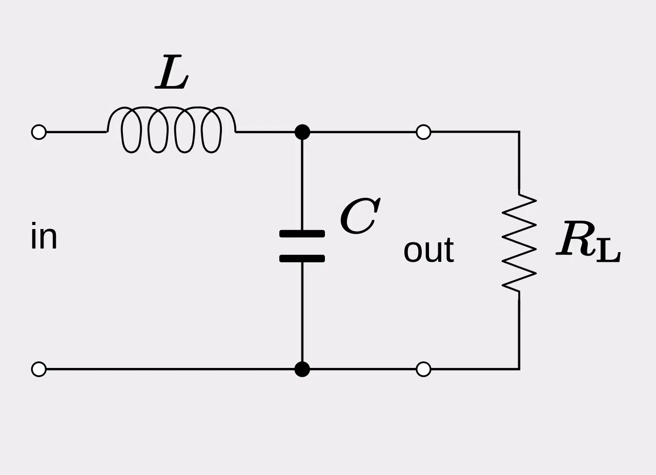
A low-pass filter (LPF) is designed to pass all frequencies below the cut-off frequency and reject all frequencies above the cut-off frequency. It is simply an RC series circuit across the input, with the output taken across the capacitor. At the cut-off frequency, the capacitive reactance of capacitor C is equal to the resistance of resistor R, causing the output voltage to be 0.707 times the Whether you're designing an entire sound system complete with a bass boost, or just want to remove high-frequency noise, the low-pass filter calculator can help you create the perfect low-pass filter circuit for your needs. Read on to learn: What a low-pass filter is; The difference between passive and active low-pass filters; and

Active Low Pass Filter: Design and Applications Circuit Diagram
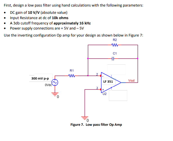
To surmount this problem, active circuit designs were introduced. When a passive low pass filter is connected to an Op-Amp either in inverting or non-inverting condition, it gives an active low pass filter design. The connection of a simple RC circuit with a single Op-Amp is shown in the image below.. First Order Active Low Pass Filter with the frequency response

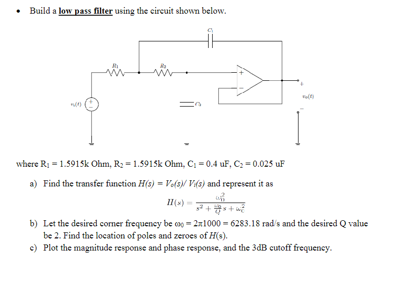
This article explores the analysis and design of passive low-pass filters. These circuits play an important role in a wide variety of systems and applications. The RC Low-Pass Filter We can attempt to create a second-order RC low-pass filter by designing a first-order filter according to the desired cutoff frequency and then connecting two

Design, Schematic, advanced guide Circuit Diagram
Designing a low-pass filter circuit may seem straightforward on the surface, particularly when approached from an instructional perspective. However, if you're in the expert's shoes, you'll understand how rigorous the thought process is to design an effective lowpass filter circuit. Even the most experienced RF and electrical engineers
Just want some suggestion design low pass filter circuit for my 40w-4ohms speaker as my subwoofer, thanks. Posted on September 09th 2022 | 10:00 pm. Reply. Karthick R. Can remove low and high pass filter from amp board. Posted on August 31st 2022 | 10:33 am. Reply. John.