Traffic Light Circuit Diagram Pdf Solved A Traffic Light System Uses Logic Gates As Part Of The Control Course Hero. Traffic Light Controller Digital Systems Design Dr Ted Shaneyfelt Pdf Free. Traffic Lights Circuit Implemented On Multimedia Logic Scientific Diagram. Traffic Light Project Using 555 Timer Ics. Simple Traffic Light Controller Sigmatone As the name of the project "Traffic Light Control Circuit" suggests, the fundamental idea of this simple electronic project is to control the traffic via lighting signals. It can be used to avoid vehicular collisions and traffic jams as the system ensures the smooth flow of traffic even on the busy routes. This document summarizes the design of a traffic light controller using state machines. It includes: 1) A literature review of state machines and programmable logic devices used to design controllers. 2) Details of an existing traffic light controller model including its specification, sequence of operation, state diagram, and state table.
The traffic light control system uses a worldwide color code (a specific color order to enable color recognition for those who are color blind). Here we design a traffic light circuit timer ICs 555 and three LED indicators. This circuit drives three LEDs with a different time delays to provide stop, wait, and go signals on road. IntroductionTraffic light controllers are essential for managing the flow of traffic at intersections, ensuring safety and reducing congestion. This article provides a detailed guide on how to design a Traffic Light Controller using the 8051 microcontroller, a popular choice in embedded systems due to its versatility and ease of use. We will cover the hardware setup, software design, and

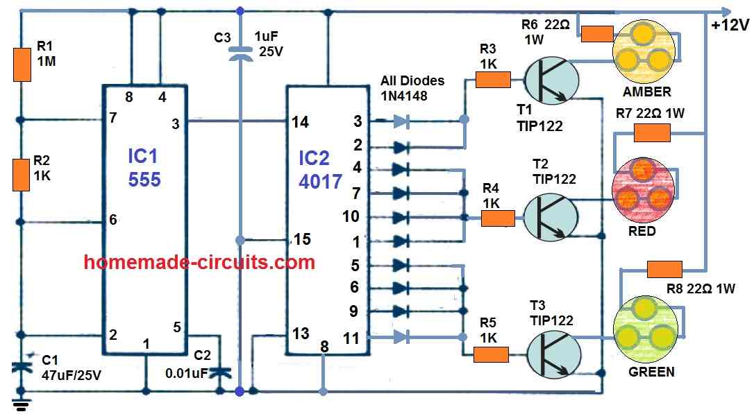
Traffic Light Control Electronic Project using 4017 & 555 Timer Circuit Diagram
When it comes to traffic light circuit design, logic gates are used to create circuits that can recognize traffic conditions and determine which lights should be green and which should be red. Typically, these logic gates function in two ways: first, they detect the number of vehicles on the road and then send a signal to the traffic signal

The idea of a basic traffic light is to control the rate of traffic. As mentioned before, modern traffic lights can monitor traffic, change light cycles for pedestrians requesting to cross, know when to change its timer for increase traffic flow, etc. Before reading on, try to think about why this design choice was made. If you think about In this challenge, we will design, create and test a logic gates circuit to control a traffic lights made of 3 LEDs (Red Amber Green). This challenge is designed to be completed with a logic board such as the Logic & Arithmetic board designed by the University of Southampton and the UK Electronic Skills Foundation.You will be able to complete the circuit with just the Logic & Arithmetic board.