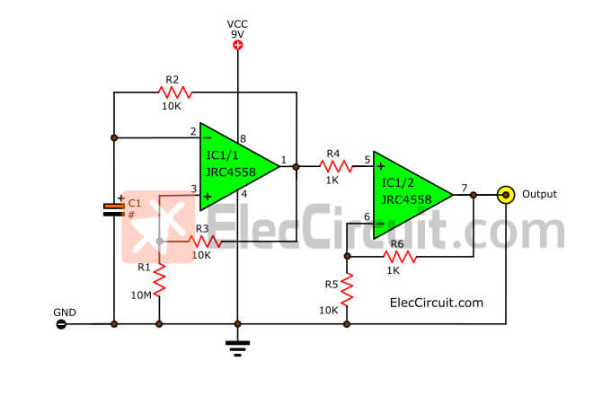
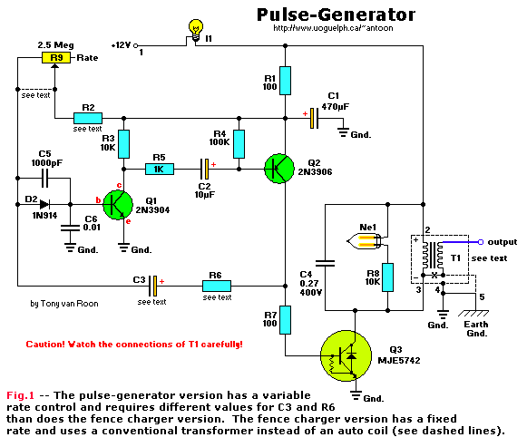
The pulse generator a Descriptive schematic of the setup b The Circuit Diagram These pulse generator circuits—a.k.a. an astable multivibrator oscillator circuit—employ a 555 timer IC, NE555 or LM555, in its astable (free-running) mode. These types of circuits are often paired up with digital logic circuits. The 555 timer IC is also very popular and simple to use, with a small eight-pin package and a supply voltage range of 4.5V to 16V. I have a DC supply (5 V) to turn some circuit on and in that circuit there is a module which uses a specific mechanism (i.e. a 2 seconds width high pulse) to turn on (even if a supply is connected, that module will turn on only by this mechanism i.e 2 seconds pulse). So I want to generate a pulse (high) of 2 seconds when that DC supply is

1. To design and simulate the pulse generator circuit that can transmit data at high frequency (0-900MHz) with the UWB technology application. 2. To apply knowledge and hands-on experiences that independently working to the project with the guidance of a supervisor. 3. To simulate and design circuit with Spectre software (Virtuoso Analog Design Although I own a somewhat expensive commercial function generator, I find that this pulse generator is the one I reach for most of the time. The generator is fairly easy to build and uses a straightforward design. It requires six integrated circuits and two transistors. In addition, you will need a power supply of 15 volts at 200 mA. In this video you will learn how to make a pulse/wave generator with varying frequency with help NE555 timer IC.For more information and circuit check the ar

Building a Pulse Generator Circuit Diagram
A pulse generator doesn't need a complicated user interface, in this case a single rotary encoder is enough. When the generator is switched on for the first time, the rotary encoder manages the frequency, press it once and the pulse width is changed. There is a problem with being able to set the frequency and pulse width separately.

Pulse Circuits - Miller Sweep Generator. The transistor Miller time base generator circuit is the popular Miller integrator circuit that produces a sweep waveform. This is mostly used in horizontal deflection circuits. Let us try to understand the construction and working of a Miller time base generator circuit. Construction of Miller Sweep Hello! For my very first instructable I wanted to show how to build a pulse generator circuit using the ever so popular 555 timer chip. This is a very simple, yet very important, circuit to build and understand. It provides a great introduction into integrated circuits and the 555 chip finds its way into many more sophisticated circuits.

Pulse Generator Using a 555 Timer : 3 Steps Circuit Diagram
The following session documents the design and fabrication of a TTL Pulse Generator for this driver circuitry, with emphasis placed on design considerations and application techniques. First segment of the pulse generator is a classic astable multivibrator circuit built around the ubiquitous NE555 timer chip (IC1). In the circuit above, we see a 555 timer configured as an astable oscillator. The 555 timer will generate the pulse width modulation signal at a specific duty cycle and switch the MOSFET transistor Q1. The MOSFET transistor in this circuit is the IRF540 MOSFET transistor.