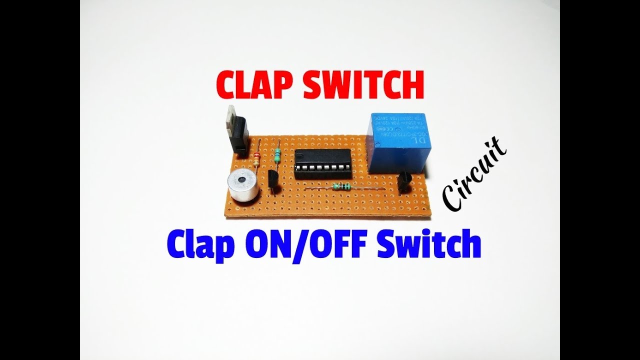
Simple Clap Switch Circuit Using Transistors Circuit Diagram Clap Switch Circuit is a basic electronics project, made from the basic components such as IC 555 Timer, BC-547 Transistors LED Resistors, Capacitors etc. Clap sound. In more simple words, the circuit is able to convert the sound energy to activate the circuit and led provide electrical energy as an output in the form of heat and light

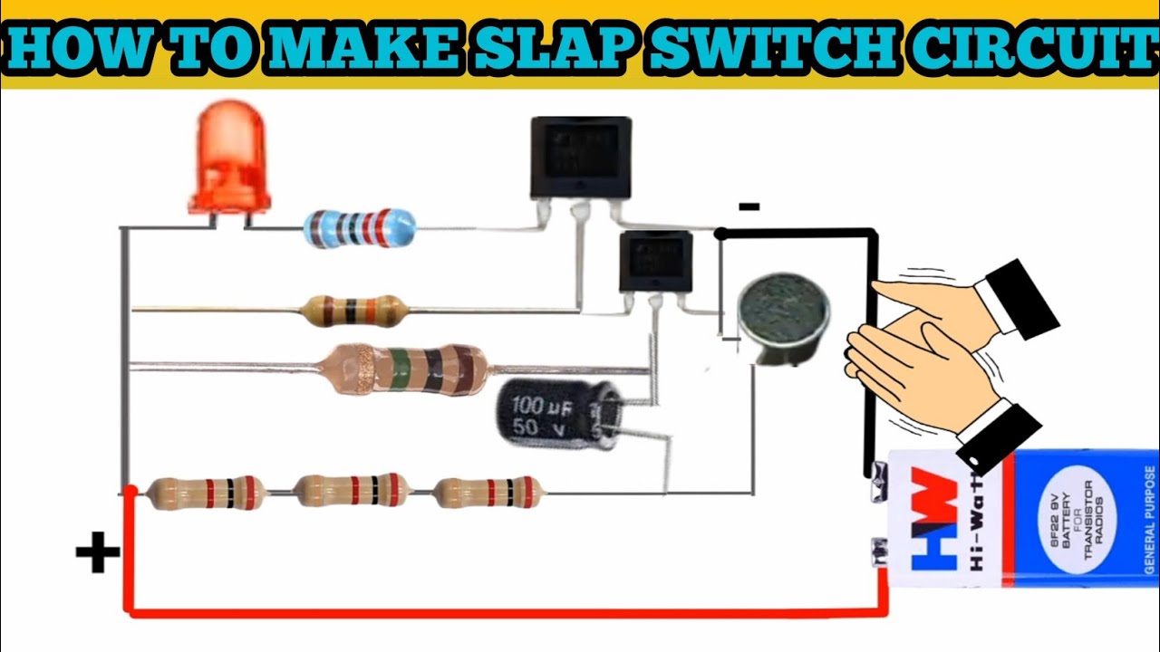
Clap On Clap Off Switch( MakeloGy )A "Clap On Clap Off" switch is an interesting concept that could be used in home automation. It works as a switch which ma To make 220V Simple clap switch circuit, watch this video until ends. We used relay to make this circuit. You will need some Raw materials that you will get It is relatively easy to make a hardware only clap on/off circuit, but I wanted to create a circuit that required two claps to switch on, and two claps to switch off. The clasps must be in quick succession, as seen in the video below, or else it does not work, which is the entire point of the circuit =) I will go into detail about the circuitry
how to make clap on off switch//simple clap on off switch Circuit Diagram
Simple Clap Switch Circuit using 555 Timer. 17845 Views August 31, 2019 Anas Ejaz . 555 In this tutorial, we will learn how to make a clap switch circuit, using a 555 Timer IC. A clap switch circuit can turn ON/OFF any electrical component by the sound of a clap. Although, the name of the circuit is a clap switch it can be turned On by any Clap switch circuits are an important part of today's home automation control circuitry, as it ventures into the domain of dynamic control of home appliances using a simple sound signal. So, Today in this tutorial, we are going to make a "Clap Switch Circuit using CD4017 Counter IC".

Additionally, review the circuit diagram for any discrepancies. 5. Can I integrate additional features into the clap switch circuit? Certainly! Feel free to explore enhancements such as timer delays or multi-device control to tailor the clap switch to your specific needs. Clap Switch working Consider the above circuit into 2 parts, the job of the left part of this circuit is to give the low signal to the right part, which has 555 timer. We already seen the right part of the circuit in " how to get the monostable output using 555 timer ". When clap switch circuit is ON and it is not producing any output i.e. both LED and buzzer are off (standby mode). The current consumed by the circuit is about 10mA (see the first image above). Working voltage of the circuit is 9v. So power (P=V*I) consumed by the circuit is 10m*9v = 90mWatt.