SelfLocking Smart Switch Module Diy Smart Home at 1299 Circuit Diagram IR Remote + Bluetooth + Push Switch Control 8 Channel Smart Switch BoardHow to Make 8 Channel Smart Switch | Smart Switch for Home Automation | EEPROM Memory Step 5: Enjoy Your Smart Switch. With everything set up and tested, it's time to sit back and appreciate your creation. Control your smart switch from your phone or computer, and marvel at the convenience it brings to your daily life. Embrace the possibilities of home automation and unleash your creativity with DIY projects like this. Embark on Home automation is becoming commonplace. But how does it work? What is the underlying tech? Let's look at how to build your own smart switch, that can be con

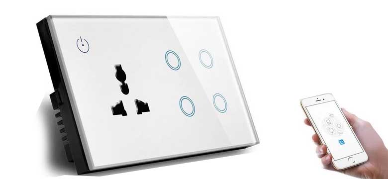
We build our own compact smart wifi switch for home automation. Now we can control the light via mobile wirelessly.Here you can find the step-by-step guide a
How To Make Smart Switch (A Step Circuit Diagram
Select Relay 1 in GPIO4 and Switch 1 on GPIO5 and click Save. After the restart, you will see a toggle switch to turn On or Off. This will control a single channel relay. To build a smart switch with more than one channel relay, you need to choose Relay 2, Relay 3, Relay 4 and Switch 2, Switch 3, and Switch 4 in the GPIOs.
With a smart switch, youll be able to control all of your electrical devices with the push of a button. What You Need to Make a Smart Switch. Making a smart switch is relatively easy to do and requires only a few pieces of equipment and software. To get started, youll need a wireless router, a wireless switch, and the appropriate software.
![Building a Smart Home from Scratch [Installing Smart Switches] – YingVannie Circuit Diagram](https://yingvannie.com/wp-content/uploads/2018/08/IMG_7884-768x1024.jpg)
DIY Smart Switch: A Handy Guide to Building Your Own Circuit Diagram
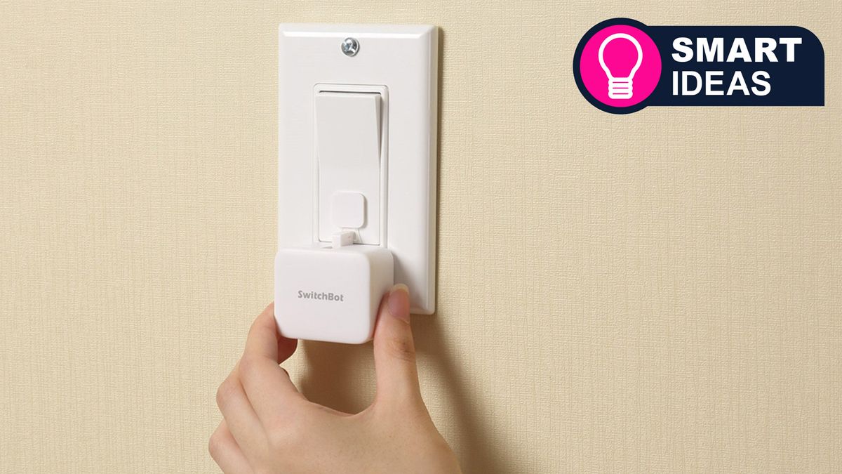
Programming the ESP for Smart Switch . To program the ESP-01 and connect it to the PC, we need a CP2102 USB breakout board. Make the below connection and plug it into the PC. Here you can find more information on how to program the ESP-01 board using Arduino IDE. Make sure the board configuration is same as the below image. Using Alexa (or your other home automation controller), you could then configure the smart button to toggle the state of the light (which, from Alexa's point of view, is your Shelly 1) on or off. I haven't personally done this exact application, but I think it's an interesting case and I'll have to make a post about it in the future. 🙂
