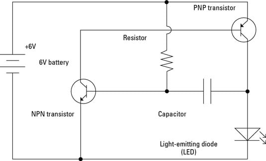
Schematic Diagram Of Simple Electric Circuit Circuit Diagram A simple electronic circuit that uses two ICs - NE 555 (as an astable multivibrator to trigger CD 4033 IC) and CD 4033 for counting purposes. Apart from two ICs and a 7 segment display (LT 543), the circuit uses a minimal set of components, 4 resistors, 1 capacitor and a diode. Circuit Diagram: Fire Alarm Circuit Diagram _____ Parts: R1 The understanding of a Simple electronic circuit will help us learn about larger projects better. Because a large project is a lot of small electronic circuits together. If you want to learn more about electronic circuits in depth or technically. I recommend reading more on Wikipedia. However, you are only an electronic hobbyist like me. Explore circuit designs for basic components such as resistors, capacitors, transistors, and LEDs, perfect for understanding fundamental concepts and building foundational skills. Our detailed guides, tutorials, and circuit diagrams provide step-by-step instructions, troubleshooting tips, and creative ideas for creating simple electronic circuits.
These free electronic circuits are properly tested and can be found with schematic diagrams, breadboard image or PCB, a detailed explanation of working principle and a demonstration video. One of the simple yet interesting connection diagrams that young engineers learn in their lab is the staircase lighting… May 13, 2024.

How to Read Circuit Diagrams for Beginners
The basic electronic circuit diagram above shows how simply a triac can be switched ON OFF through an ON/OFF switch and also ensure safety to the triac by using the load itself as a buffer stage. The R1 limits the current to the triac gate, while the load additionally provide the triac gate protection from sudden switch ON transients, and

Figure 1 - Simple resistor circuit. The voltage source symbol shown is a battery, but any DC power source could be substituted. The current which is represented by "I", with the arrow shown, will flow from the positive terminal of the voltage source V1 through the wire, down through R1 and then into ground. The wiring diagram of a simple LED flashlight or LED torch circuit is presented in the above diagram. It simply consists of a couple of AAA, Another simple electronic circuit project suitable for all beginners is shown below, which is a simple continuity tester circuit. It works with a couple AAA cells in series or with a 3V DC, and can be
Simple Electronic Circuits Circuit Diagram
At No.8 in our list of Top 10 Simple Electronics project comes the famous LED Chaser circuit. An LED chaser circuit is a repeating sequencer usually made by combining a simple clock circuit with a counter circuit. It is widely used in places such as advertising displays and in running-light 'rope' displays in small discos, etc.