Raspberry Pi Cyber Security Projects Circuit Diagram Connect the DATA output of the transmitter to GPIO 17 of the Raspberry Pi (rev B in my case)Connect the DATA output of the transmitter to GPIO 17 of the Raspberry Pi (rev B in my case) 3. The 433MHz receiver output is 5V so use a simple voltage divider circuit (220 ohm/440 ohm) to drop the voltage down to 3.3V. Create an affordable and customizable smart home security system using the Raspberry Pi 5. This guide covers hardware setup, sensor connections, and programming, enabling you to monitor your home from anywhere. Ideal for DIY enthusiasts, this project brings real-time security alerts, live video, and remote access to your fingertips. Building a Smart Home Security System
Learn how to design and implement a home security system using Raspberry Pi as a server and various sensors. The project report covers the software and hardware aspects, the conceptualization, the issues, and the results.
based smart home security system Circuit Diagram
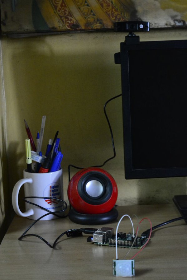
Warning! RPI IOs do not accept 5V, you should use eg. a TTL logic converter to decrease voltage coming from RFID or PIR sensors. My choice was a 74HC4050. Ok, theoretically you could be able now to run rpi-alarm.py with: nohup python rpi-alarm.py & But before that you need to edit the code and change IDs to your RFID tags and email address too. Learn how to design a simple and easily installable device using Raspberry Pi 3, Web Cam and PIR Motion Sensor to detect and alert any visitor at your home. The device connects to Google Cloud and sends email alerts to the house owner.
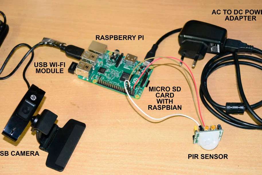
In this IoT based Project, we will build a Home Security System using PIR Sensor and PI Camera. This system will detect the presence of Intruder and quickly alert the user by sending him a alert mail. This mail will also contain the Picture of the Intruder, captured by Pi camera. Raspberry Pi is used to control the whole system.

DIY Home Security + Automation Using a Raspberry Pi Circuit Diagram
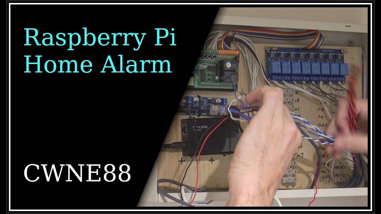
In November last year — I started building a DIY security alarm system, using a Raspberry Pi as the controller. My plan was to make a self-sustained system, using proper alarm hardware — like PIR sensors and sirens. Integration with Home Assistant would be an add-on, not a requirement. I wanted the system to be as redundant and fault-tolerant as I could make it. This is a pretty long story
Although the Raspberry Pi would only be running the alarm system alongside other OS/user processes, we opted to assign the alarm system a higher priority to minimize the risk of missing RF messages. To achieve this, we utilized the "nice" command with the "-10" flag, which assigns a priority level above the default (max priority "-20

Powered Home Security System with Raspberry Pi Circuit Diagram
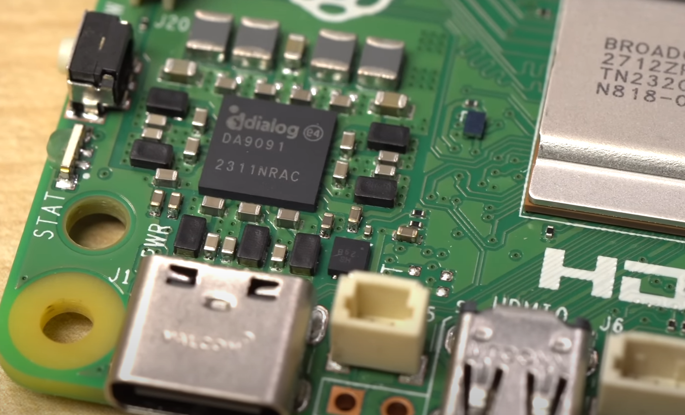
In this post, we'll create a sophisticated home security system using a Raspberry Pi and AI capabilities. Our system will recognize family members, detect strangers, and identify package deliveries, all while sending real-time web notifications. Hardware Requirements. Raspberry Pi 5 (here is the one I use by default)