Mayfly Inside 1 Surface Mount vs Through Hole Web Circuit Diagram Through Hole mounting is inserting component leads into drilled holes in a bare PCB. Before the emergence of SMT in the 1980s, through-hole technology was the industry-standard configuration method. The fact that Surface Mount is more efficient and less expensive has led many to believe that THT will become obsolete.

Through-hole component leads, which run through the board and connect a board's layers, have been replaced by "vias" -- small components which allow a conductive connection between the different layers of a PCB, and which essentially act as through-hole leads. Some surface mount components like BGAs are higher performing components with There are two leading methods for assembling a board — surface mount technology vs. through-hole technology. Overview of the PCB Assembly Process. The most commonly cited example of thru-hole mounting process benefits is the fact that thru-hole mounted components offer enhanced reliability. Because the leads go all the way through the

Surface Mount vs Through Hole: A Detailed Comparison Circuit Diagram
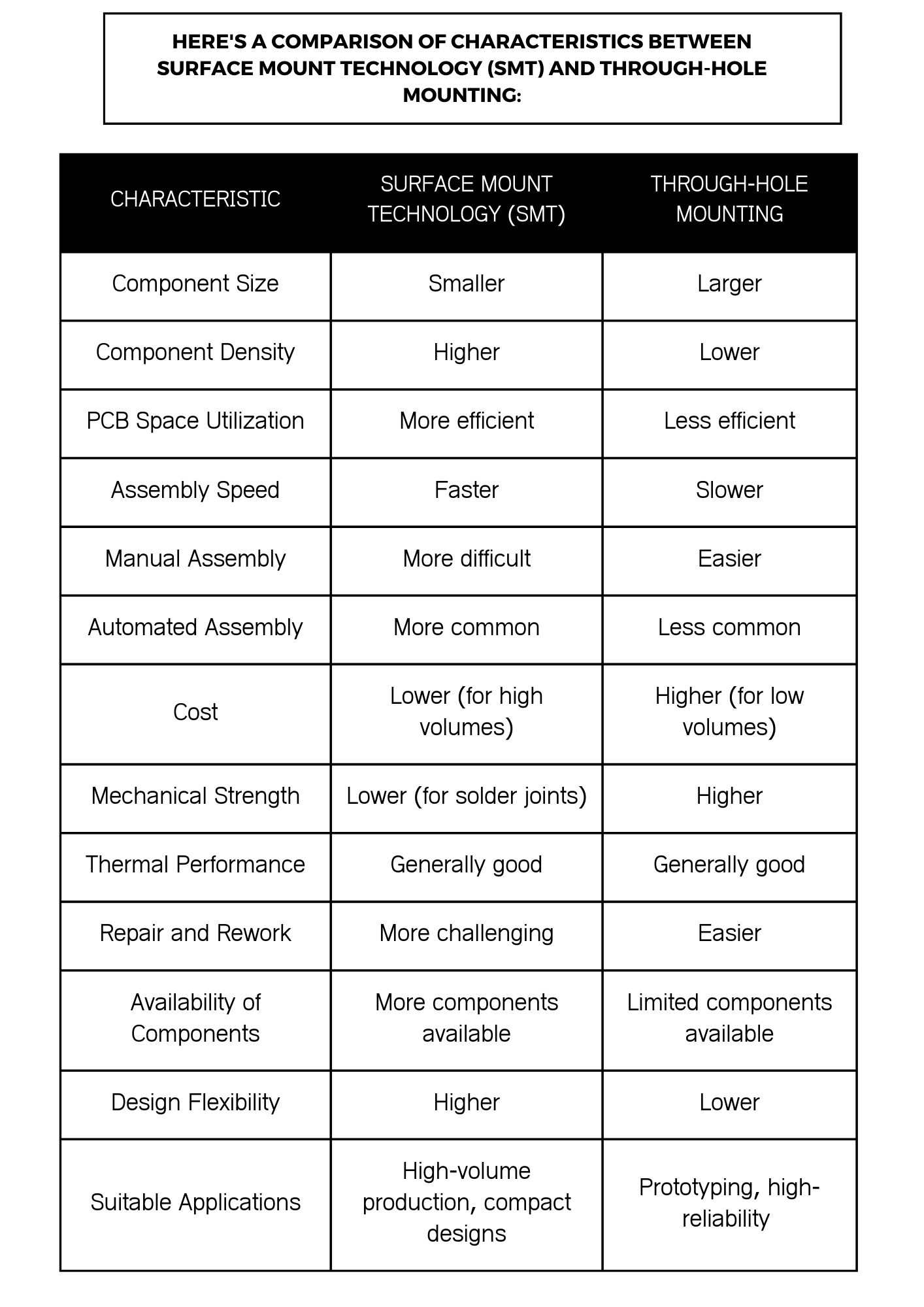
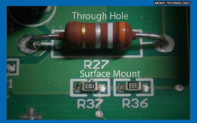
The choice between Surface Mount Technology and Through Hole Technology is pivotal in electronics manufacturing. Each method offers distinct advantages and is suited for different applications. By understanding the key differences and evaluating your specific needs, you can optimize your manufacturing process and achieve superior results. SMD vs THT - An Overview. Surface-mount technology (SMD) and through-hole technology (THT) are two primary methods for mounting electronic components onto printed circuit boards (PCBs). SMD components are soldered directly onto the PCB's surface, while THT components pass through holes in the PCB and are soldered on the opposite side.
Surface Mount Components: SMT components are generally less adept at handling extreme environmental conditions due to their surface-only solder connections. 3. Industry Applications Through-Hole Components: Through-hole technology finds its niche in high-reliability industries like military and aerospace. These sectors require components that Before the emergence of SMT in the 1980s, through-hole technology was the industry-standard configuration method. However, Surface Mount is more efficient and less expensive, it leds many people to believe that THT would become obsolete. Although through-hole components represent the older of the two technologies, there are still valid reasons
Surface Mount vs. Through Hole: What are the Differences Circuit Diagram
Key Differences of Through Hole vs Surface Mount. In the through hole versus surface mount debate, knowing the key differences will help you choose the right method for the intended application: More components can be mounted on the board, in part because SMT components are smaller, and in part because both sides of the board can be utilized. Surface Mount Technology (SMT) represents a paradigm shift in electronics assembly, enabling the direct placement of components onto the surface of printed circuit boards (PCBs). This method diverged from the traditional through-hole technique by eliminating the need for wire leads to pass through the PCB. Instead, surface mount components are soldered onto pads on the surface of the board. These surface mount components, known as Surface Mount Devices (SMDs), come in a variety of shapes and sizes, but they are generally much smaller than their through-hole counterparts. The SMT process begins with the application of solder paste to the PCB.