Introduction and Voltage Measurement Circuit Diagram This instructable will cover a project build for an Arduino based Solar MPPT charge controller. It has features like LCD display, Led Indication, Wi-Fi data logging and provision for charging different USB devices. Basics on MPPT charge controller. 2. Buck circuit working and design calculation. 3. Testing the Buck Circuit. 4. Voltage and The MPPT controller operates on a simple yet powerful principle. It continuously adjusts the electrical operating point of solar panels to extract the maximum possible power, regardless of fluctuating environmental conditions. This adaptive approach results in significantly higher efficiency compared to traditional Pulse Width Modulation (PWM) controllers, especially in scenarios where the So let's start our Solar Charge Controller circuit. Disclaimer: Handling electricity carries inherent risks. It's essential to have the appropriate skills to manage it safely. MPPT Solar Charge Controller. & Thanks for your comment. Reply. Seun · 13/07/2021 at 2:36 am Please Sir, can I use either p- or n- channel MOSFETs, because I can
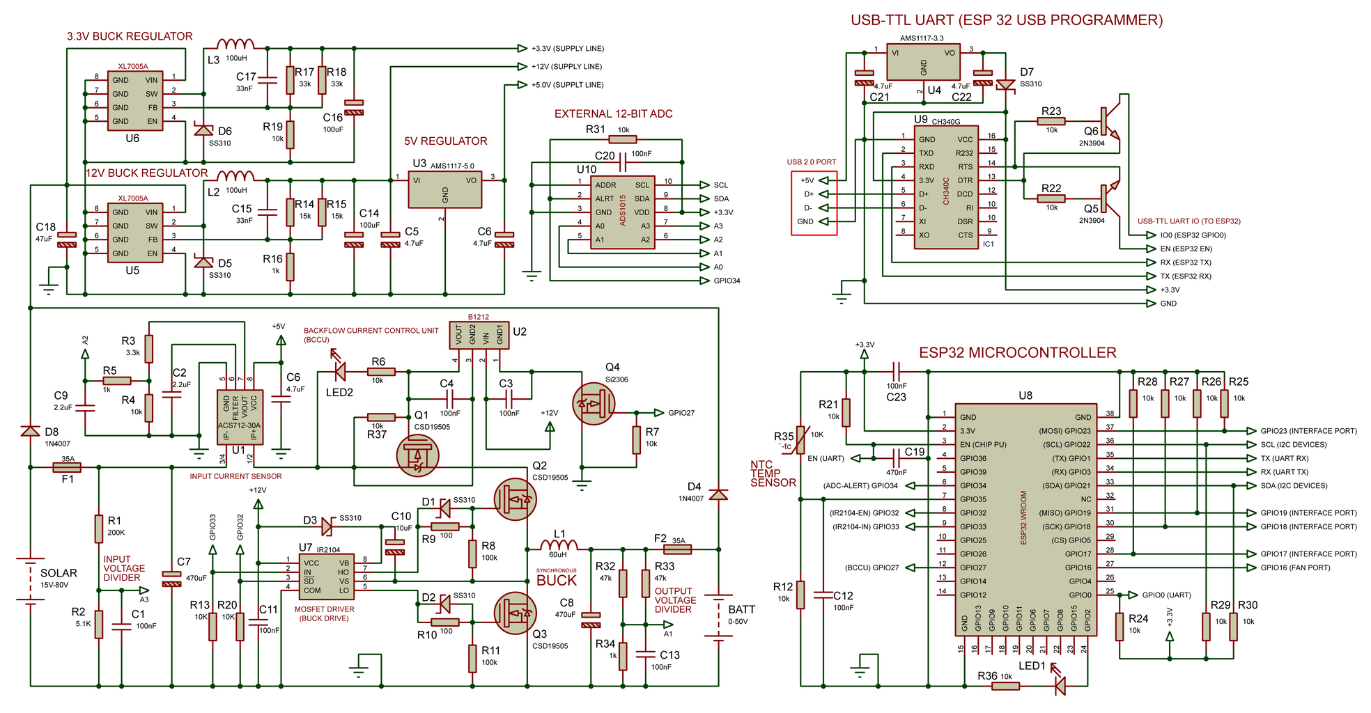
I have a question on Design #1 in your "3 Best MPPT Solar Charge Controller Circuit for Efficient Battery Charging". Under nominal conditions (25 degc, 1000 W / sq m) my solar panel is spec'ed for a Vmp = 19.65v and an Imp = 4.33A. With a 12v battery, will your design develop ~19.65v on the solar panel itself ? 1kW Arduino MPPT Solar Charge Controller (ESP32 + WiFi): Build a 1kW WiFi MPPT Solar Charge Controller, equipped with phone app datalogging telemetry! (Android & IoS) It is compatible with 80V 30A solar panel setups and all battery chemistries up to 50V. Premium commercial grade MPPTs use the same circuit topology. It turns out, you are not Figure 2 Maximum power point tracking (MPPT) Charge Controller Circuit Diagram The output current of a solar module varies directly with the amount of light (irradiance) as shown in Figure 3a . The maximum power that can be delivered will be greater at a higher irradiance, by reducing the load and maintaining the voltage at a constant level.

Designing of MPPT Solar Charge Controller using Arduino Circuit Diagram
The MPPT charge controller circuit diagram is an essential component of any solar panel system, and understanding how it works can help you make the most of your solar energy. From understanding the basics of the circuit to selecting the right charge controller for your particular application, proper installation and use of the MPPT controller MPPT solar charge controllers have 2 main circuits, so they basically perform 2 operations: Maximize the power output of the solar array through Maximum Power Point Tracking technology. Decrease the voltage of the solar array to match the voltage of the battery while increasing the current by the same ratio.