How to make simple wireless using RF module Tutorial 28 Circuit Diagram Wireless Remote Control. Now to do something useful - create a wireless digital output control. Our transmitter will have two buttons, and our receiver will control two LEDs via digital outputs. Naturally this is an example, you can use this as a base to control other devices if required. You will need: One set of 315MHz or 433MHz wireless data

The image of the short-range RF modules will be used since the connection is the same and the Long-range RF modules do not have a fritzing package. Transmitter Schematics. The transmitter schematics is quite simple, we only need to connect a push-button and the transmitter of the 315MHz transceiver to the Arduino as shown in the image below. In this project, a wireless transmitter and receiver system using RF modules (RF Transmitter and RF Receiver) is implemented. An RF Transmitter and Receiver pair is used for wireless communication. The wireless data transmission is done using 433 MHz Radio Frequency signals that are modulated using Amplitude Shift Keying (ASK) Modulation technique.
How can I use 433MHz RF Modules and HT12E/HT12D to create a wireless ... Circuit Diagram
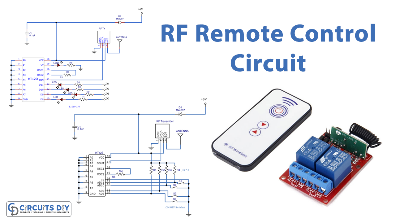
Here I'll show you how to make an approximately 100 meter range RF remote control circuit using RF modules, without the help of any microcontroller stage. To begin the assembly you will have to procure the following readymade RF modules and the respective encoder and decoder chips , for the present project we use the HOLTEKs modules: common RF channels and sniffable codes (insecure) scrambled sequential digital codes (secure) called Rolling Code method. IR with common IR carrier frequencies but unique codes (like TV remote) BUY a "Rolling-code" door opener with RF remote, Rx and switches, then reverse-engineer everything! (from electronics, mechanics, UX, packaging to quality).
The latter provides Manchester encoding/decoding routines to balance the voltages used for the RF receiver gain averaging circuit. This instructable however, describes how you can make a Pic microcontroller talk to a cheap RF module (433MHz) through its USART port, to send data over a wireless link to another Pic.
Simple RF Remote Control Circuit without Microcontroller Circuit Diagram
HT12D Typical Connection Diagram. DIN: Connected to the RF receiver module.; VT (Valid Transmission): Goes HIGH when valid data is received. Data Outputs (D0-D3): Drive relays, LEDs, or other control circuits. Working of HT12E and HT12D. HT12E (Encoder) Takes 4-bit parallel data and an 8-bit address.; Encodes and transmits serial data via the RF module when TE is low.