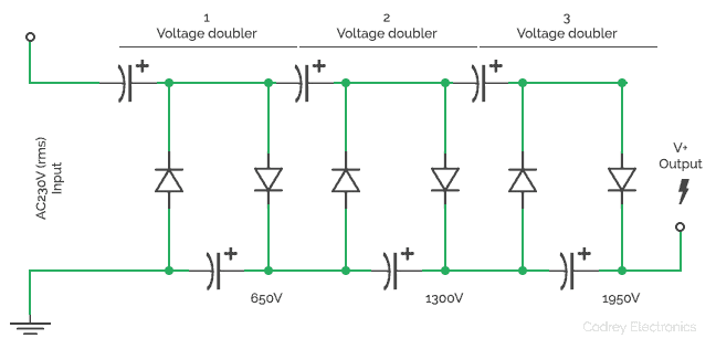
How to Make a Voltage Multiplier 6 Steps Circuit Diagram The most commonly used multiplier circuit is the half-wave series multiplier. All multiplier circuits can be derived from its basic operating principles. Thus, the half-wave series multiplier circuit is shown in Figure 1 to exemplify general multiplier operation. The example shown in Figure 1 assumes no losses and
So how does it work. The circuit shows a half wave voltage doubler. During the negative half cycle of the sinusoidal input waveform, diode D1 is forward biased and conducts charging up the pump capacitor, C1 to the peak value of the input voltage, (Vp).Because there is no return path for capacitor C1 to discharge into, it remains fully charged acting as a storage device in series with the Here is some info about voltage multipliers if you want to know how they work. If not, then skip to the parts list. Definition - "A voltage multiplier is an electrical circuit that converts AC electrical power from a lower voltage to a higher DC voltage by means of capacitors and diodes combined into a network." - Wikipedia
How to Make a Voltage Multiplier : 6 Steps Circuit Diagram
The voltage doubler is a type of the voltage multiplier circuit. Most of the voltage doubler circuits with few exceptions can be viewed in the form of a higher order multiplier at a single stage. Also, a greater amount of voltage multiplication is achieved when there are cascading identical stages which are being used together. Villard Circuit
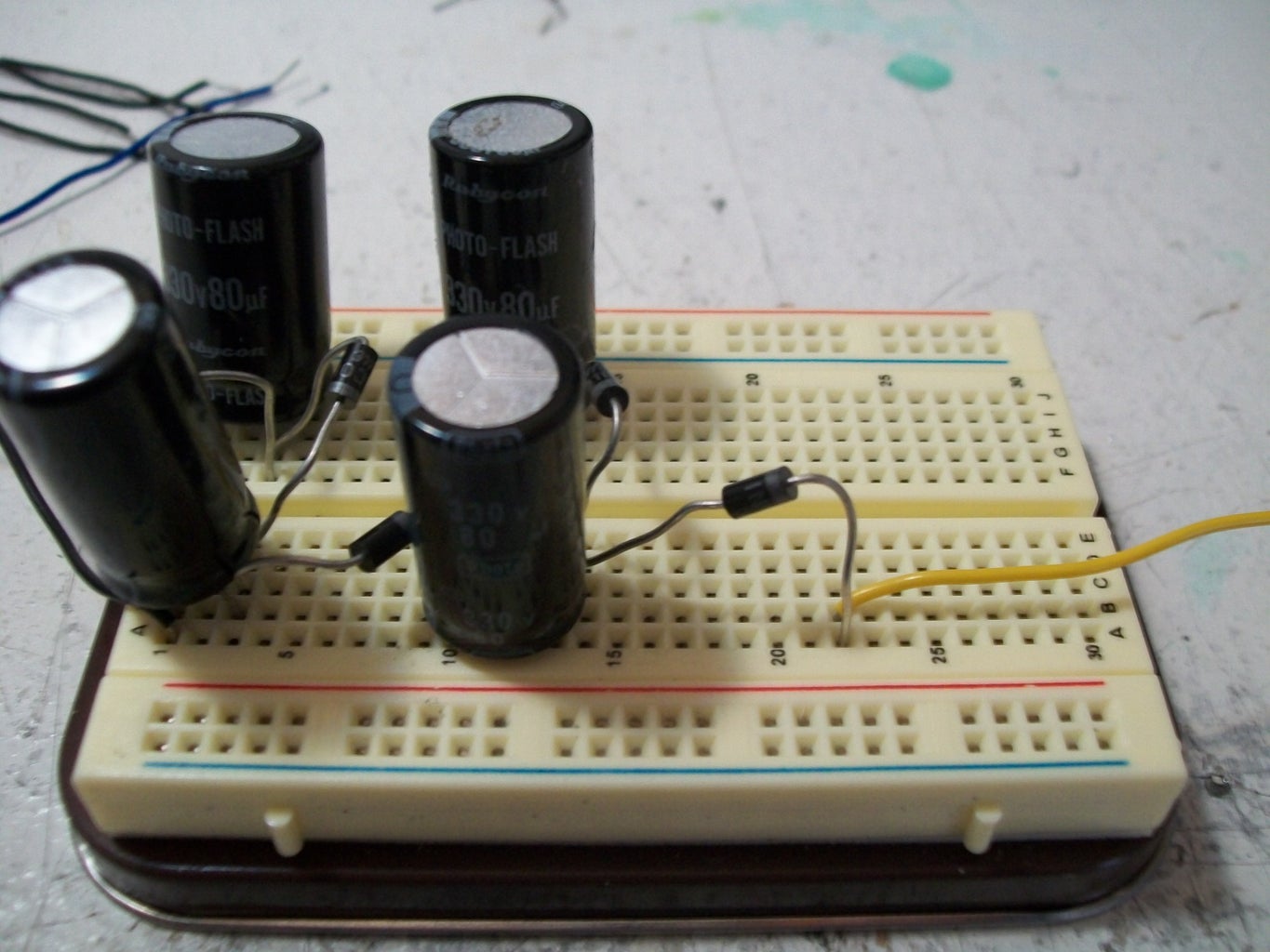
Circuit of Voltage Multiplier. The circuit of a simple voltage multiplier is shown in Figure-1. It is clear that a voltage multiplier is simply a combination of diodes and capacitors. The low voltage AC signal is input to the circuit from the power source (transformer in this case). This AC voltage is converted into DC voltage by diodes and
Circuit, Operation, Types, and Applications Circuit Diagram
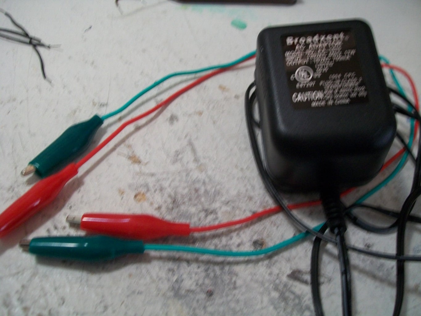
- DC voltage source consisting of mains transformer and rectifier, in this case with output voltage of 15V and current of 5A. - AC high voltage source, with an output value of 5 to 10 thousand volts. This assembly consists of a driver circuit and a flyback transformer from an old TV. In my case it is a "Plasma Speaker" device I have made before. A voltage multiplier is a specialized rectifier circuit producing an output that is theoretically an integer time the AC peak input, for example, 2, 3, or 4 times the AC peak input. Thus, it is possible to get 200 VDC from a 100 Vpeak AC source using a doubler, and 400 VDC from a quadrupler. Any load in a practical circuit will lower these voltages. the dimension of voltage as shown in Figure 1. Figure 1: Basic Analog Multiplier and Definition of Multiplier Quadrants . From a mathematical point of view, multiplication is a "four quadrant" operation—that is to say that both inputs may be either positive or negative, as may be the output. Some of the circuits
Voltage Multiplier Circuits are devices that are designed to generate an output voltage that is a multiple of the input voltage. They are often used to achieve higher voltage levels than older circuits that were developed in the past, especially in situations where efficiency and compact design are very critical.