How to Build a Smart Home System with Arduino and WiFi Circuit Diagram Wifi + Voice Controlled Home Automation with ESP8266 & Android. This post is all about Wifi & Voice Controlled Home Automation Using NodeMCU & Android. Here we will do the same, but instead of using Alexa, we will develop our own App on an Android smartphone to control our locally (using buttons or voice), our home devices.
Scalability ensures that your smart home system can grow and adapt as new technologies and devices become available. 7. Budget: Set a budget for your smart home system and carefully consider the cost of the devices you're considering. While quality and functionality are crucial, it's important to choose devices that align with your budget. How to Control Everything In Your Smart Home. You can control the basic functions of many smart home devices directly via Wi-Fi and a companion mobile app. and allow you to create a whole

How to Create a Smart Home: A Complete Guide for Beginners in Home ... Circuit Diagram
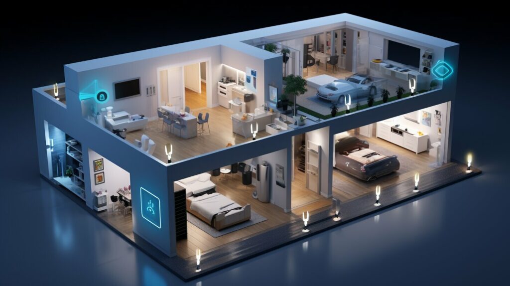
Almost all smart-home devices require a reliable Wi-Fi connection. What you need to know are the two most-used frequencies: 2.4 GHz and 5 GHz. Most smart-home devices operate on the 2.4-GHz Determining the Scope of Your Smart Home System. Once you have chosen a smart home platform, the next step is to determine the scope of your system. Start by identifying the rooms or areas in your home that you want to automate. Common areas include the living room, kitchen, bedroom, and bathroom.

A robust home Wi-Fi network is essential for the seamless operation of smart home devices. Mesh Wi-Fi systems like Google Nest Wi-Fi and Eero Mesh Wi-Fi ensure strong and reliable internet coverage throughout your home, supporting the connectivity needs of multiple smart devices and maintaining smooth operation. Benefits of Smart Homes
Smart Home Automation Using Blynk & ESP32 IoT Projects Circuit Diagram
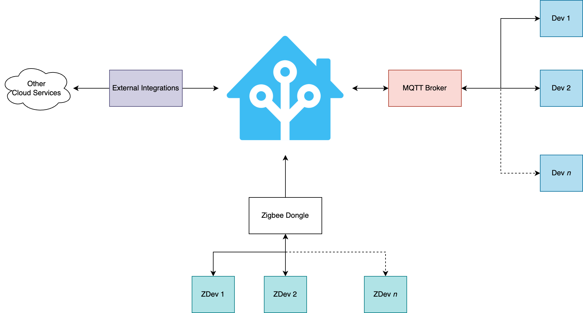
Once you have chosen the right smart home devices, the next step is to create a smart home network that will connect and control these devices. It involves two main components: choosing a smart home hub and setting up a Wi-Fi network. Choosing a Smart Home Hub

During the article, I have shown all the steps to make this home automation system. This ESP32 control smart relay has the following features: 1. Control home appliances with WiFi (Blynk App) 2. Control home appliances with manual switches. 3. Monitor real-time feedback in the Blynk App. 4. Control home appliances manually without internet.
