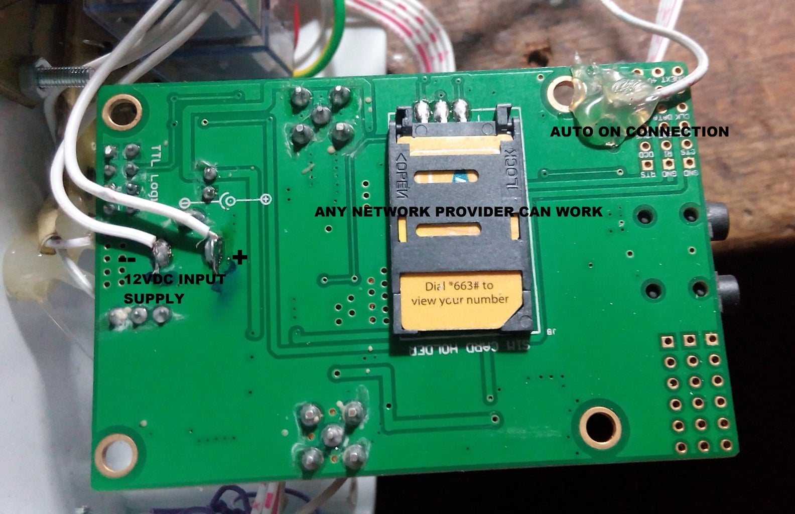
Google Map Vehicle Tracking System using GPS GSM modem Circuit Diagram GSM Module (SIM800l) The GSM module facilitates communication with the vehicle using the Global System for Mobile Communications (GSM) network. It enables sending and receiving SMS messages, which allows for remote control and monitoring of the vehicle. The module is connected to the Arduino board to pin numbers 2 and 3. In this video, we'll explore how to build a GSM and GPS-based vehicle anti-locking system using Arduino. This project aims to enhance vehicle security by aut
After reading this string using Arduino extract the required data from string and then sends it to mobile phone using GSM module via SMS. This information is called latitude and longitude. GPS used 3 or 4 satellite for tracking the location of any vehicle. Fig. 2: Prototype of Arduino based Vehicle Tracking System Step 5: Type "TRACK VEHICLE" to the Sim on the Sim Module. Switch ON the hardware. Download the code. check the Network range on the GSM module with the blinking of the network led. Type "TRACK VEHICLE" as SMS and send to the sim module in the GSM Modem. Step 6: You Can Receive the Response SMS From GSM Module

GPS+GSM Based Vehicle Tracking System using Arduino Circuit Diagram
In this video, we will learn about how to make an Arduino Based Vehicle Tracking System using GPS & GSM Module. Most of the vehicle tracking system available

This project implements a Vehicle Tracking System using Arduino along with GPS and GSM modules. It allows tracking the vehicle's real-time location and sends this data to a web server for monitoring purposes. This system can be used for fleet management, theft prevention, or simply monitoring vehicle movement. GSM Modem. This vehicle tracking system using GPS uses a SIM300 GSM modem. GSM modem transmits and receives the data. Modem SIM300 is a tri-band GSM/GPRS engine that works on frequencies EGSM 900 MHz, DCS 1800 MHz, and PCS 1900 MHz. Transmit pin TXD and receive pin RXD of the GSM modem are connected to the microcontroller (IC2) via MAX232 (IC3).
Vehicle Tracking System Based on GPS and GSM Circuit Diagram
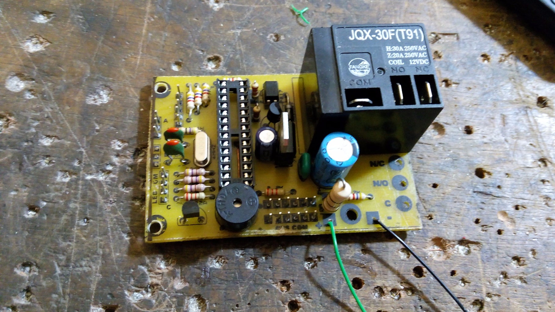
The system can be installed or hidden in your vehicle at a suitable location. After installing this circuit, you can easily track your stolen vehicle using a mobile phone. The author's prototype is shown in Fig. 1. Fig. 1: Author's prototype Circuit and working. Circuit diagram of the GPS- and GSM-based vehicle tracking system is shown in
The Board has a 32-bit ATSAMD21 controller from Atmel which can be programmed using Arduino IDE. You can also make this project using Neo-6M GPS Module & SIM 800/900 GSM Module with Arduino UNO Board. But this will make the device size large. We will discuss in detail about this Arduino GPS & GSM Based Vehicle Tracking System. Arduino retrieves a vehicle's current location using the GPS module. The board stores the latitude and longitude of the current location and transmits them to the ThingSpeak server using the GSM network via the SIM900A modem. The modem generates an HTTP post for the address of the ThingSpeak server to transmit the vehicle's location data.