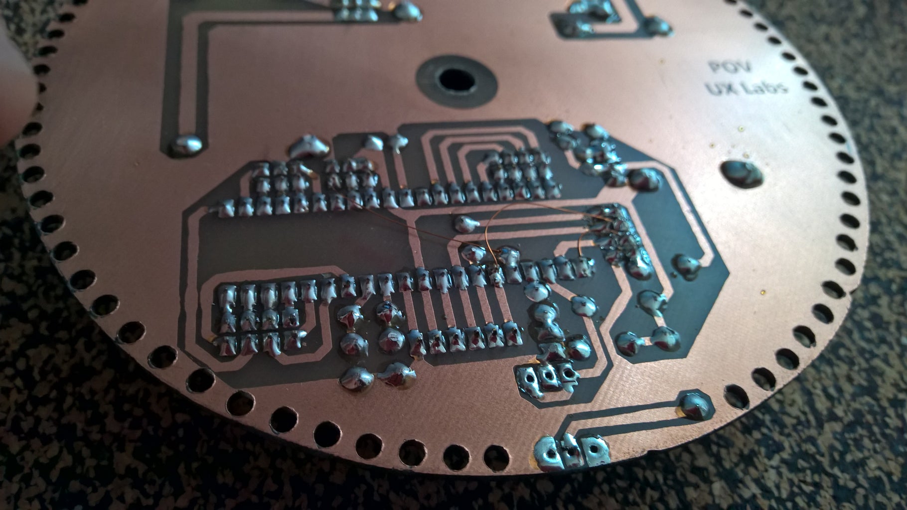
Globe Persistence of Vision 8 Steps with Pictures Circuit Diagram Thirdly, solder the LED bulbs to the dot board strip on the other side. Step 4. Now, attach the resistors to the LED anode side. After, solder the resistors for the LED anode pins. Step 5. Now, solder the LED cathode pins together. Time for a fun-filled, easy-peasy Japan-easy to make a project! Today, we're going to show you how to make an LED POV Display. POV, an acronym for the persistence of vision, is a kind of optical illusion in which a visual image seems to persist even when the light from it ceases to enter our eyes and this makes it super cool! DIY Persistence of Vision: In This Project I Will Introduce You To Perspective Of Vision Or POV Display With A Few Supplies Such As Arduino And Hall Sensors To Make A Rotating Display Which Displays Anything You Like Such As Text,Time and Other Special Characters. Step 3: Build the Circuit.
Persistence of Vision (PoV) Display Using Arduino : Time for a fun-filled, easy-peasy Japan-easy to make a project! Today, we're going to show you how to make an LED POV Display. POV, an acronym for the persistence of vision, is a kind of optical illusion in which a visual image seems to persist even… What we are going to learn here today is how to make a POV display or Persistence-Of-Vision display. It is made out of just 6$ worth of components. This tutorial gives will teach you how to make a simple and a cheap Arduino POV display. We can use this display as a pocket-sized portable message showing device and tabletop clock.

How to Make a DIY POV Display (Persistence of Vision) Using Arduino ... Circuit Diagram
Time for a fun-filled, easy-peasy Japan-easy to make a project! Today, we're going to show you how to make an LED POV Display. POV, an acronym for the persistence of vision, is a kind of optical illusion in which a visual image seems to persist even when the light from it ceases to enter our eyes and this makes it super cool! 1> Assemble LED's on breadboard as follows-Cathode to GND power rail (blue rail)-Anode to individual nodes. 2> Connecting current limiting resistor - Add 220 ohms resistor to anode of each resistor. 3> Make connections with the Arduino Digital pins from the resistors connected in series with the LED's as follows. LED 2=>D2. LED 3=>D3. LED 4=>D4
+(V1.00)+-+Page+2.jpg)
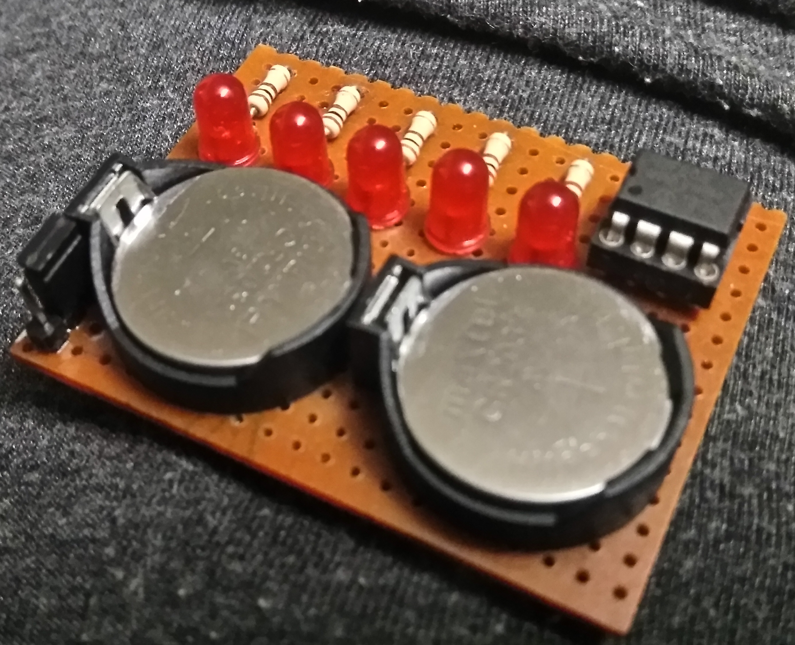
LED 5Pcs. (here I showed green led but. red led is better than green led) 220ohm Resistor 5Pcs; Lipo/Old mobile battery; 100rpm gear motor and wheel (for rotary mechanism) Circuit diagram: Cut the perf board to the appropriate size. Then connect the LEDs and solder them as shown in the figure below.
POV (Persistance of Vision) Display : 7 Steps (with Pictures ... Circuit Diagram
This project will show you how to make your own LED POV Display (Persistence of Vision), persistence of vision display, persistence of vision led clock. Open Resourses. Quarky Series. Quarky; Quarky Mars Rover; Circuit Diagram Fritzing Diagram; Make the connection as shown: LED: LED0: D2 of nano; LEd1: D3 of nano; LED2: D4 of nano; LED3: D5
