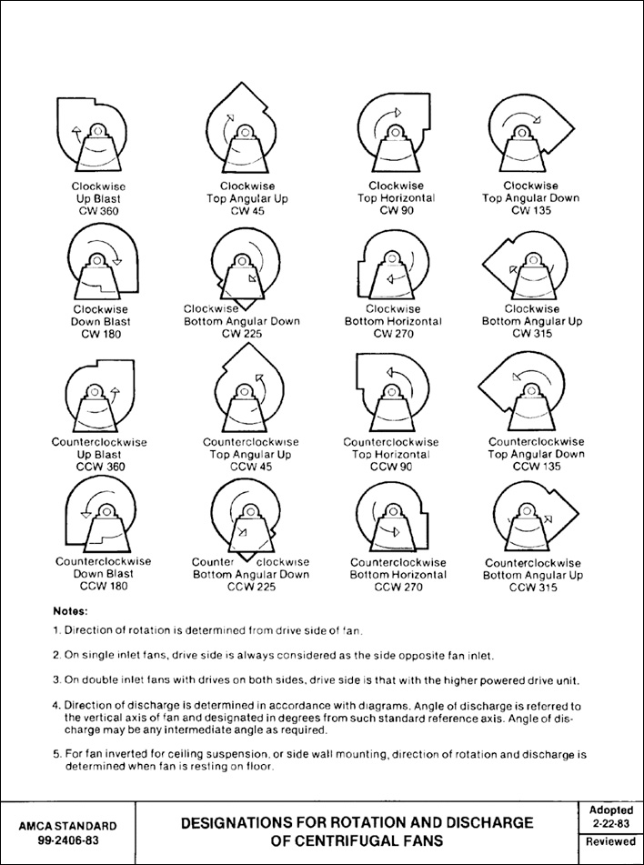
Engineering Projects BIDIRECTIONAL ROTATION OF AN EXHAUST FAN MOTOR Circuit Diagram The motor rotates in a certain direction with the value of Speed. Experiment Summary¶ In this experiment, you can also control the motor to rotate or not. Just connect pin 1, 2EN of the L293D to an I/O port of the control board. Set 1, 2EN as High level, and the motor will start rotating; set it as Low level, it will stop the rotating. How to Change the Rotation Direction Step 1: Determine the Current Rotation Direction. Observe the fan from the motor side and note whether it is rotating clockwise (Rd) or counterclockwise (Lg). Step 2: Disconnect Power Supply. To ensure safety during the process, disconnect the centrifugal fan from its power source.
A few seconds after the upload finishes, the fan runs at full speed for 4 seconds, then the fan will reverse at a slower speed for 2 seconds and then stop. Manually control the rotate direction and speed of the Mini Fan. In this example, we use a potentiometer to control the speed of the motor and a push button to control the direction. To control the direction, set IA and IB to different logic levels: IA = HIGH and IB = LOW for clockwise rotation. IA = LOW and IB = HIGH for anticlockwise rotation. To control the speed, apply a PWM signal to either IA or IB while keeping the other pin at a constant logic level. If you power the Arduino UNO module, the servo motor will start to totate and the Fan module will start to spin, you can adjust the fan speed with a potentiometer. Watch the video for the detail demonstration. Congratulations! You have completed your project with Visuino.
How to Use fan motor L9110: Examples, Pinouts, and Specs Circuit Diagram
In this lesson, we'll learn how to control a DC motor (like a small fan) The L293D allows us to control the direction of the motor rotation—both clockwise and counterclockwise. Since DC motors require more current than the Pico can provide directly, we'll use an external power supply to safely power the motor. Circuit Diagram
When pushed once, the fan should rotate at minimum speed (pwm = 100), pushed a second time speed 2 = 178, pushed a third time speed 3 = 255 and fourth time speed =0. (2) the direction control button should be default = clockwise when turning on the fan but should be able to reverse direction at the same speed setting it is pressed on. The fan will remain on until the button is pressed again. In oscillation mode, the model checks to see if the fan button has been pressed (or if the fan is currently on) and that the oscillation button has been pressed. Once the buttons debounce, the fan will begin to rotate in the counterclockwise direction if possible. Couldn't be better! Just with three handy gadgets, you can make a simple fan with speed control and oscillating function. Materials: one DC motor. one servo. one rotary encoder module. circuit diagram: Working principle: when we rotate the rotary encoder, we get a digital quantity. By rotating left and right, this digital quantity can be

【Arduino】Simple fan with speed control and oscillating function Circuit Diagram
Once the motor is easily accessible, you'll want to use a screwdriver to rotate the fan's direction switch, which is usually located at the top of the motor. This will change the fan's direction of rotation. Once the direction switch is properly adjusted, you'll be able to reattach the fan blade and then reinstall the capacitor.