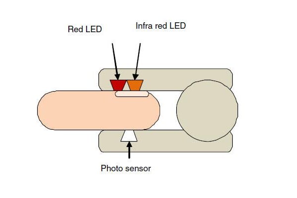
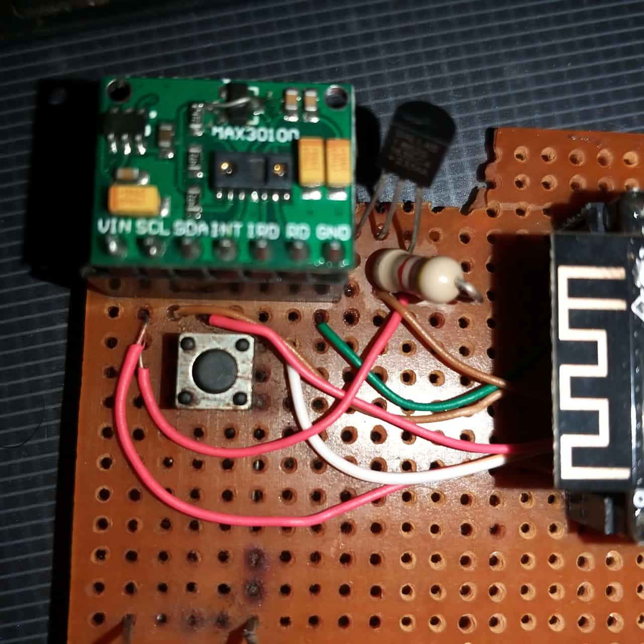
DIY Pulse Oximeter Circuit Diagram The oximeters can also build By using Max30100 Sensor which is specially design for measuring pulse and oxygen saturation in blood. It's not that critical to make an pulse oximeter using it, since It combines two LEDs, a photodetector, optimized optics, low-noise analog signal processing to detect pulse oximetry and heart-rate signals. and I2C interface.
The "SpO2" reading on a pulse oximeter shows the percentage of oxygen in someone's blood. If your home SpO2 reading is lower than 95%, call your health care provider. I want to minimize this DIY design, so here in the PCB I am using Arduino Nano MCU, 16*2 LCD, MAX30100 with charging circuit. This is tested schematics, but the LCD only

Arduino Pulse Oximeter : 35 Steps (with Pictures) Circuit Diagram
In this detailed tutorial, learn how to build a pulse oximeter using MAX30100 sensor with Arduino and display the Heart rate BPM and blood oxygen level termed as SpO2 values on serial monitor, LCD display or OLED Display.. So before getting started into the project lets learn about the principles, working and applications of the MAX30100 sensor and learn how the sensor calculates the Heart
Arduino Pulse Oximeter: Pulse oximeters are standard instruments for hospital settings. but it's incredibly important not to wire anything backwards or you will very likely damage things on the circuit boards. Make sure power is turned off when you are connecting the circuits (It really is the safest way to avoid problems).
Arduino Pulse Oximeter (With Code) Circuit Diagram
A pulse oximeter is a non-invasive device used to measure the oxygen saturation level (SpO2) in the blood and pulse rate. It works by emitting light through a part of the body, usually a fingertip, and measuring the amount of light absorbed by the blood. There are many pulse-oximeter sensors available in the market for medical purposes, and in one of our previous projects, we also made an IoT-based Heart Rate Monitor where the data is sent from a device to the cloud. Now, here in this project, we will do the same thing but differently with a different mindset. We will make the project using a MAX30100 sensor and an OLED display that will In this project we are going to learn how to make a pulse oximeter with the ability to measure heart rate and blood oxygen. First let's make the circuit, make sure to follow the exact circuit diagram since the program is designed accordingly. 2.

Basic pulse oximeter circuit. The signal contains DC and AC components. The DC component is due to constant reflective matter such as skin, muscle and bone, and venous blood. When a body is at rest and motion is less of a factor, the AC component comprises mainly of reflected light from the pulsation of artery blood. The AC component depends on

DIY Pulse Oximeter by interfacing MAX30100 sensor with Arduino Circuit Diagram
Fortunately, pulse oximeters are relatively easy to make at home with some basic knowledge of electronics and an understanding of how the circuit works. The first step is to gather the components. You'll need an infrared LED and photodiode, resistors, a microcontroller with an analog-to-digital converter, and a display.
