DIY Low Cost Home Automation Using Esp8266 6 Steps Circuit Diagram With a little creativity and some programming skills, you can come up with your own ideas for projects that use the ESP8266 to make your life smarter, more convenient, and more connected. IoT Esp8266 Its compact form factor and ease of use have made it a favorite among hobbyists, students, and professionals alike. The ESP8266 NodeMCU is powered by the ESP8266EX chipset, which integrates a 32-bit Tensilica microcontroller, providing ample processing power for IoT applications. It also includes built-in Wi-Fi connectivity, making it a perfect
In the world of IoT (Internet of Things), getting started with NodeMCU ESP8266 is an excellent way to dive into smart applications and connected devices. The NodeMCU ESP8266 is a popular, low-cost, and user-friendly development board designed for building IoT projects. With built-in Wi-Fi capabilities, a microcontroller, and GPIO pins, it The ESP8266 incorporates an 802.11b/g/n HT40 Wi-Fi transceiver, allowing it to connect to a Wi-Fi network to access the internet (Station mode) or to create its own Wi-Fi wireless network (Soft access point mode) to which other devices can connect.Power. Because the ESP8266's operating voltage range is 2.5V to 3.6V, the board includes an LDO voltage regulator to keep the voltage stable at 3.3V. All the ESP8266 projects are explained with step-by-step instructions with a components list, circuit diagram, source code, and all other required resources and information needed to build those ESP8266 projects. You can also explore projects with different IoT platforms like IFTTT, and Blynk. Amazon, Google Home, etc.

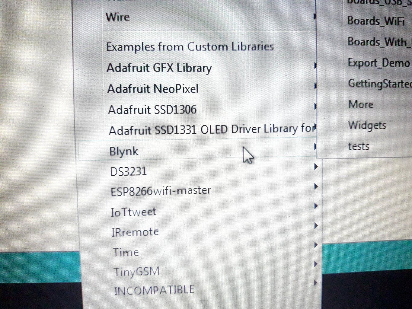
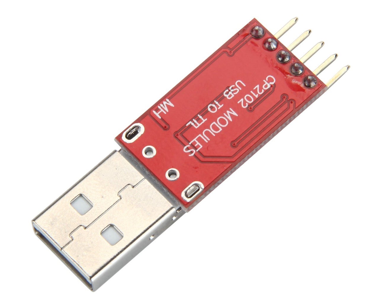
How to program an ESP8266 Circuit Diagram
Connect the LDR sensor to pins on Nodemcu ESP8266. 1. Connect a jumper wire from any one of the end to NodeMCU VIN pin. 2. Connect a jumper wire from another end to NodeMCU A0 pin. 2. Connect a resistor to the NodeMCU GND . Detection of an object. Connect the IR sensor to pins on Nodemcu ESP8266. 1. Connect a jumper wire from VCC to NodeMCU VIN An ESP-Mesh-based smart home system was developed in the previous research using the ESP8266 feature with 3 different nodes, such as mechanical (door lock), electrical (fan, generic power switch
We have more than 150 ESP8266 NodeMCU Tutorials and project ideas as well as a Premium eBook Home Automation using ESP8266. Using the next quick links, you'll find all our ESP8266 Guides with easy to follow step-by-step instructions. Each tutorial includes circuit schematics, source code, images and videos.

Smart Street Light Using NodeMCU and IOT ThingSpeak Circuit Diagram
This finishes the complete smart parking system using the ESP8266 NodeMCU Module and different peripherals. You can use other sensors also in replacement of Ultrasonic and IR sensor. There is a vast application of Smart Parking System and different products can be added to make it more smart. I discovered ESP8266 a few years ago. Since then, I'm fascinated by it. I use it wherever it fits 🙂 For less than $2, you can have a fully functional microcontroller with a full TCP/IP stack. It can run your device and be connected to a WIFI at the same time. It is the perfect solution for IoT applications and Smart Homes.
