DIY ECG Circuit Diagram ECG signal will vary in amplitude depending on the placement of the recording electrodes and the individual, but are typically on the order a few millivolts when recording from the wrists. (While it is not necessary for this setup, signal amplitude can be increased by placing electrodes on the chest, but the trade-off is noise from lung movement.)-
In 2019 I released a YouTube video and blog post showing how to build an ECG machine using an AD8232 interfaced to a computer's sound card. At the end of the video I discussed how to use a 555 timer to create a waveform roughly like an ECG signal, but I didn't post the circuit at the end of that video.
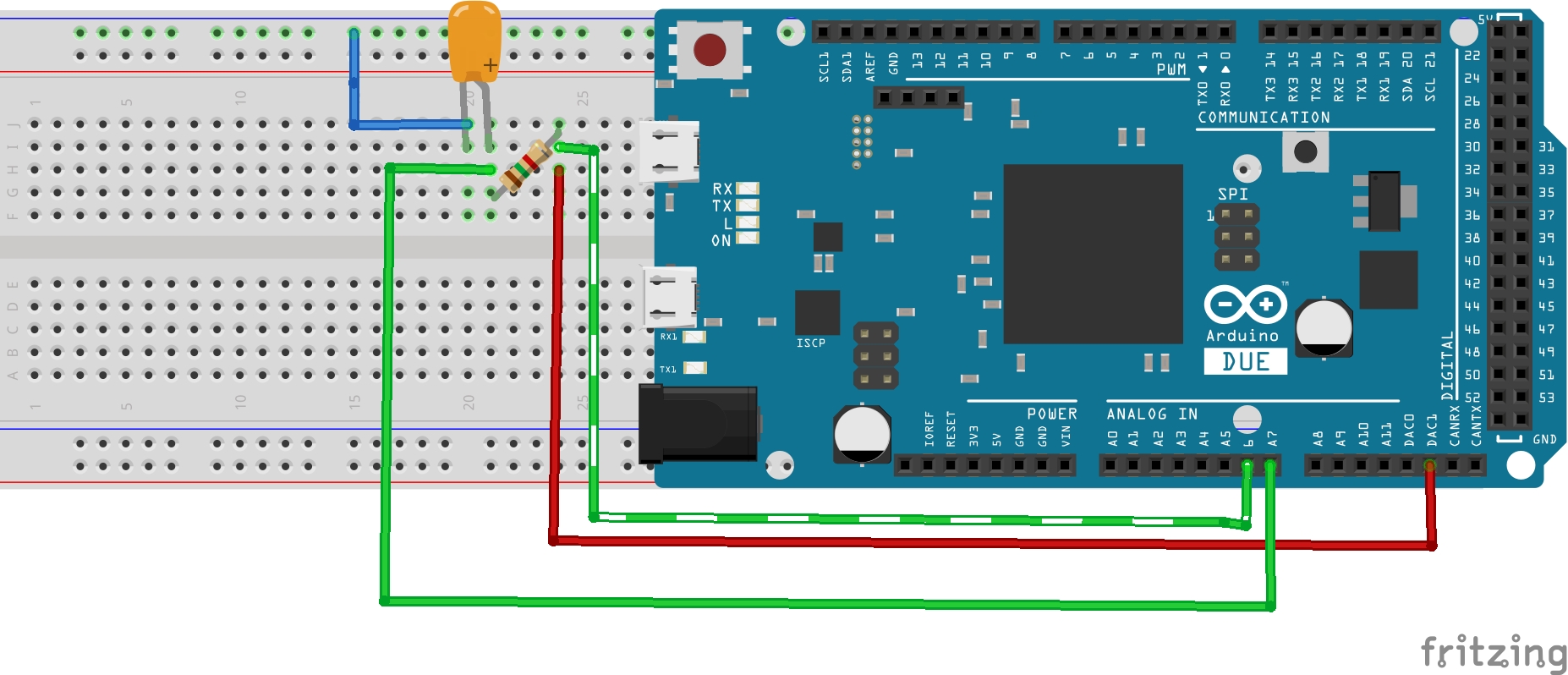
Time ECG Monitoring System Using AD8232 and Arduino UNO Circuit Diagram
As you select the device will be connect to application and the ECG graph is shown as the below image. Method 3: Interfacing AD8232 ECG sensor with ESP32 to show the graph over Internet. In this method, learn how to connect the ESP32 with ECG sensor and display the data i.e, ECG graph over internet and can be seen live from anywhere around the
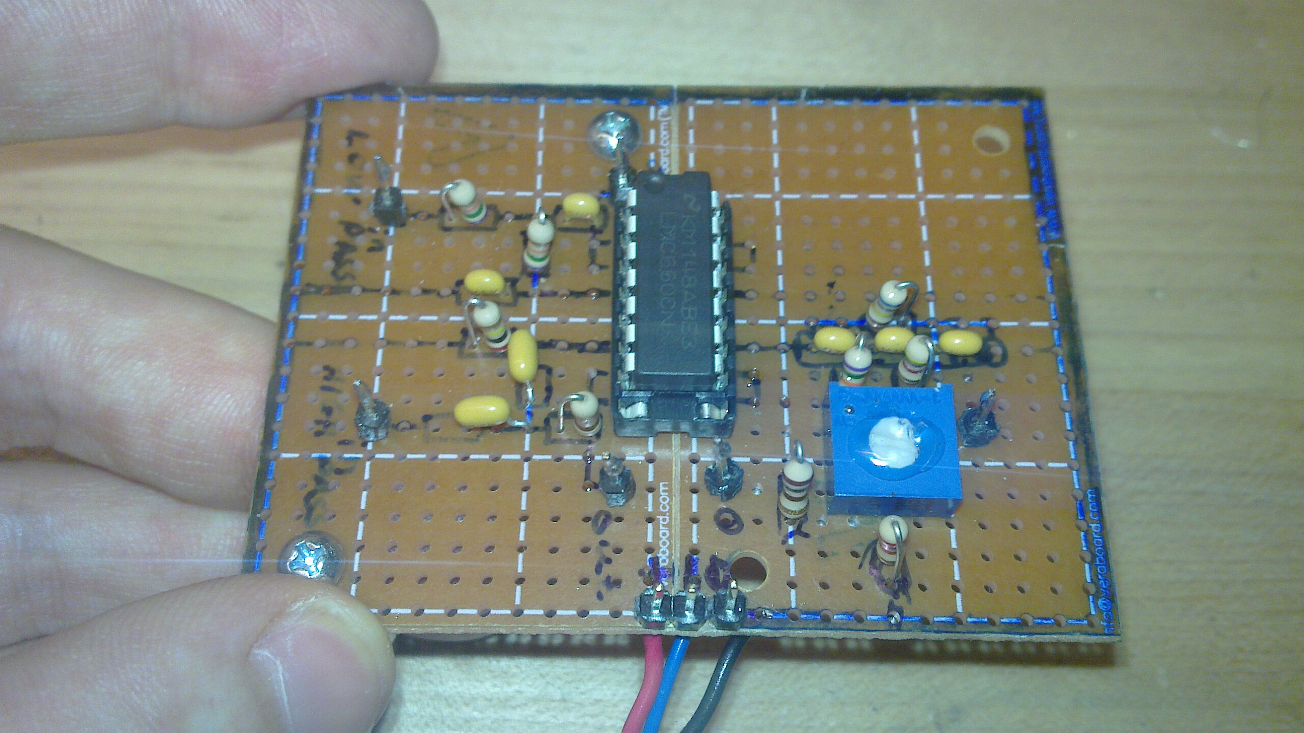
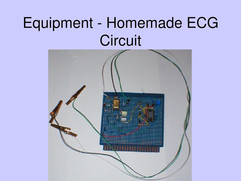
This tutorial is an in-depth guide on how to make your own simple EEG circuit. Along with monitoring brain wave concentration, the final circuit can also be used as an ECG, as a way to see your heartbeat trace. The circuit will use 3 electrodes - 2 to measure a voltage difference across your scalp, and one as a reference to ground. Our EKG circuit includes a standard instrumentation amplifier (INA 128) with a simple low-pass RC filter and a high-pass RC filter, both designed using the standard LM741 ICs. The filters can be connected in sequence without a DC offset since we are using a simple DC battery power as the power source, which introduces insignificant DC shifts.
AD8232 ECG Module with Arduino Circuit Diagram
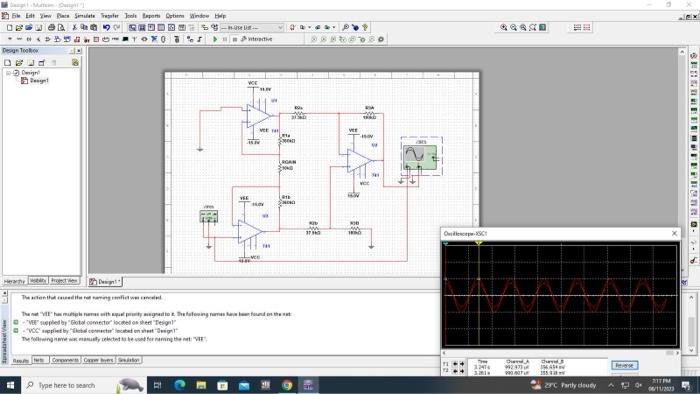
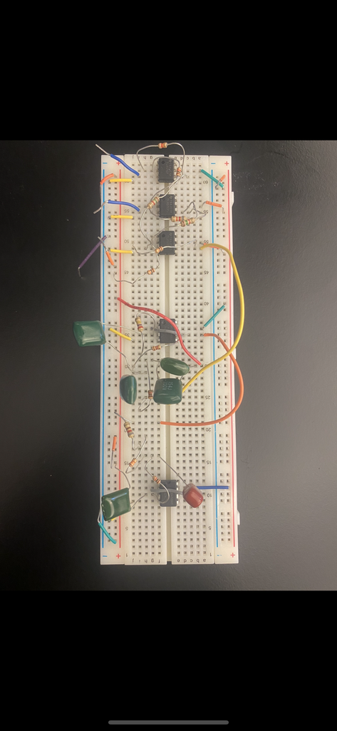
Featuring an instrumentation amplifier made up of three 741 op-amps and an assortment of resistors.#ecg #circuit
An electrocardiogram signal can be simulated using a waveform generator. Select the appropriate in-built ECG waveform function using the user interface. The signal should have a low amplitude input of 1 - 5 mV and a frequency of around 1.2 Hz. Connect the generator to the input terminal of the integrated circuit.