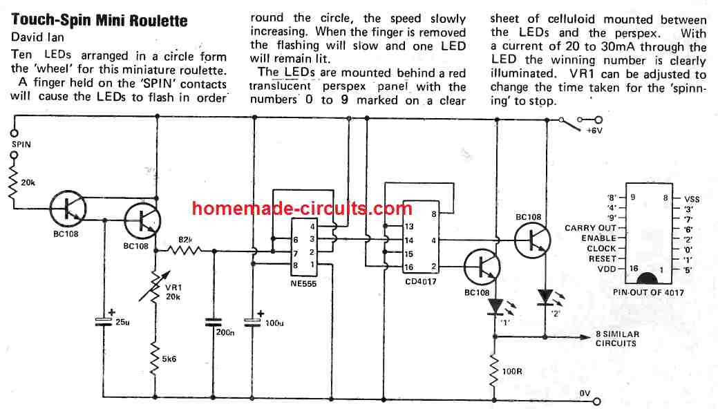
Creating Mini Digital Roulette Games with Arduino Circuit Diagram Roulette is a casino game named after the French word meaning little wheel. In this game, players may choose to place bets on either a single number, various groupings of numbers, or the colors red or black. So here In this tutorial, we are going to make an "LED Roulette Circuit using 555 Timer IC". The main component of this circuit is a NE555 Timer IC.
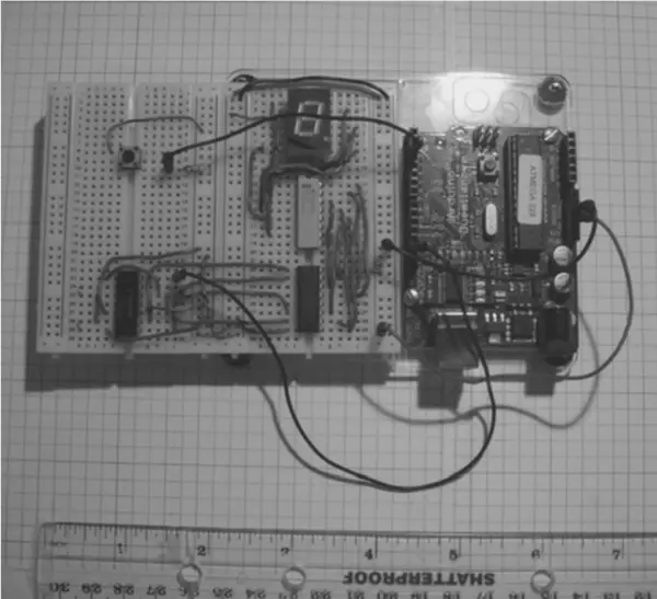
Analysis of the Touch-Spin LED Roulette Circuit. This circuit has the following features: A touch-spin switch to communicate with the user. clock pulses produced by a NE555 timer integrated circuit. The LEDs are sequenced using a CD4017 decade counter. Transistors BC108 are used to power the LEDs. Circuit Diagram. Click on the circuit diagram for full resolution image. How This Circuit Works. Watch the video above, for better understanding on how this LED roulette circuit works. Terms Used: Negative rail corresponds to 0V and Positive rail corresponds to the voltage of power supply used. When you touch both the touch-contacts: Read also: DIY Flashing Bicycle LED Taillight Circuit. 2. The 10 LED roulette circuit using IC-4017 and IC-4011. In Figure 2 is the 10 LED roulette that a game of my son. How it works. When entering the power supply circuit, and switch S1 (Start), which is attached press release switch off. Then the current is flowing through R1, R2, and C2.

How to Make Simplest Arduino European Roulette Game ( 37 Leds ) Circuit Diagram
The circuit of a simple roulette game presented here is surely one of the simplest as far as the electronic casino home games are concerned. To learn more just follow the instructions to build your own simple electronic game, also find out how the IC 555 is configured as a voltage controlled oscillator (VCO) to produce a real roulette wheel effect. Working Explanation. Now we're going to blink the LEDs in a roulette configuration (circle shape), as we've used 8 LEDs that are linked by the 4017 IC output pins according to output series, start from zero and go up to 10 but we're just using 8 output pins as the number of LEDs is 8 and it gets the clock pulse orIn Astable mode pulse data from the 555 timer IC. 555 Timer Roulette: This project uses a 555 timer to create a circuit that simulates a spinning roulette wheel. The circuit involves a 555 timer and a 4017 IC decade counter. is much like the very complicated circuits used inside of Casinos for their electronic gambling games. Electronic roulette wheels with LEDs likely use very similar
How to make simplest Arduino European Roulette Game ( 37 Leds ) Thanks to the "Charlieplexing technique", the construction is drastically simplified and apart from Arduino and LEDs, five resistors, a button and a speaker are needed. There are two popular roulette wheels: American and European. The European wheel has only one zero while the American wheel has two zeroes. Also the number sequence is different. This time I will present you how to make an electronic version European roulette, where the movement of the ball is simulated by successive lighting of LEDs.