Arduino Digital energy monitor for your house Circuit Diagram Monitor your energy consumption through the Arduino IoT Cloud using a MKR WiFi 1010, a MKR 485 Shield and a Modbus compatible energy meter. Nov 11, 2022 17372 views
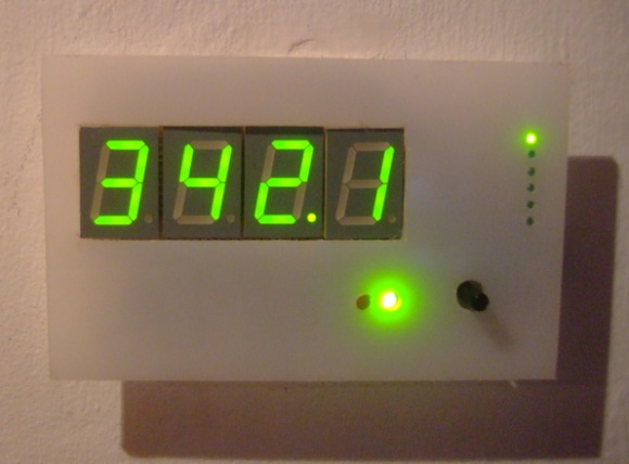
First a quick look at the installed setup: The Display. The display unit consisting of 4 large green led 7 segments. On the right is a 6 mode - mode chooser so that you can select by turning the potentiometer (bottom - right) whether the display shows real power, apparent power, power factor, RMS Voltage, RMS Current, frequency or cumulative kWh used.
Simple Arduino Home Energy Meter Circuit Diagram
CT Sensors - Interfacing with an Arduino. Assemble the components per the diagram above. Step 3: Upload the Arduino Sketch The sketch is the software that runs on the Arduino. The Arduino converts the raw data from its analog input into human readable values, then sends them to the serial port monitor. c) Open the arduino serial window** You should now see a stream of values. These are from left to right: real power, apparent power, rms voltage, rms current and power factor. See also: How to build an Arduino energy monitor - current only. EmonTx Arduino Shield: Our open-hardware energy monitoring Arduino compatible shield featuring the above
I had started building an energy monitor based on what I had read on openenergymonitor.org. I am using an Arduino Uno Rev 2, and four SCT-013-030 CTs. My main goal is to calculate kw used by my heat pump (Condenser, AHU and heat strips) and my hot water tank. Here is a list of the items which you need in order to complete this project. The LCD screen is optional, it is obviously useful if you plan on permanently installing or using your energy meter however you can just make use of the Arduino serial interface to display the information. An Arduino (Uno used here)- Buy Here
How to Build an Arduino Energy Monitor Circuit Diagram
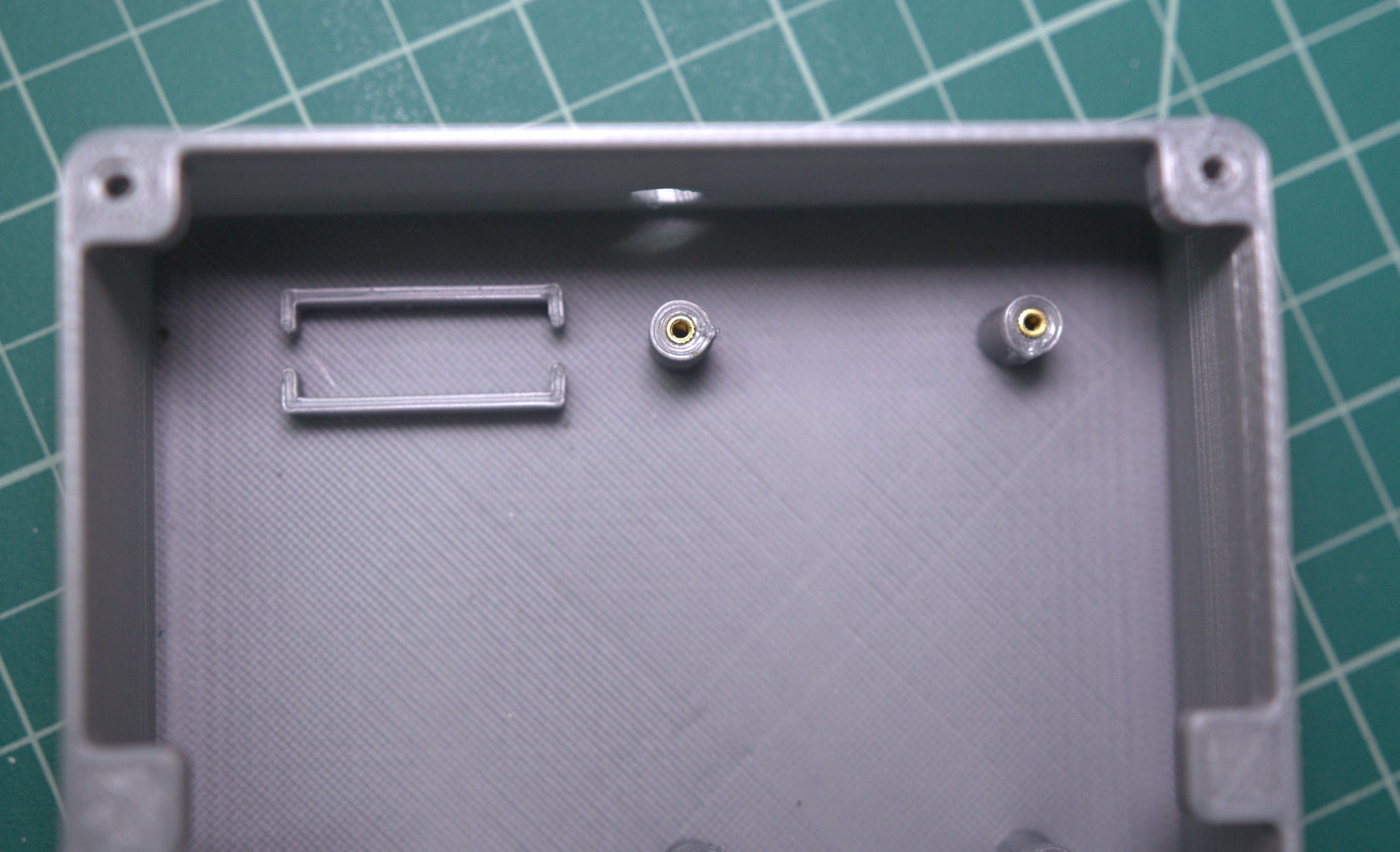
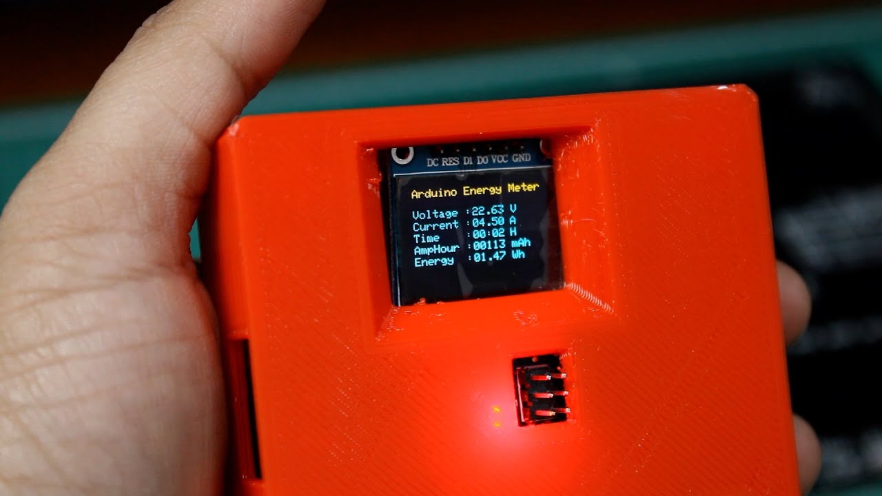
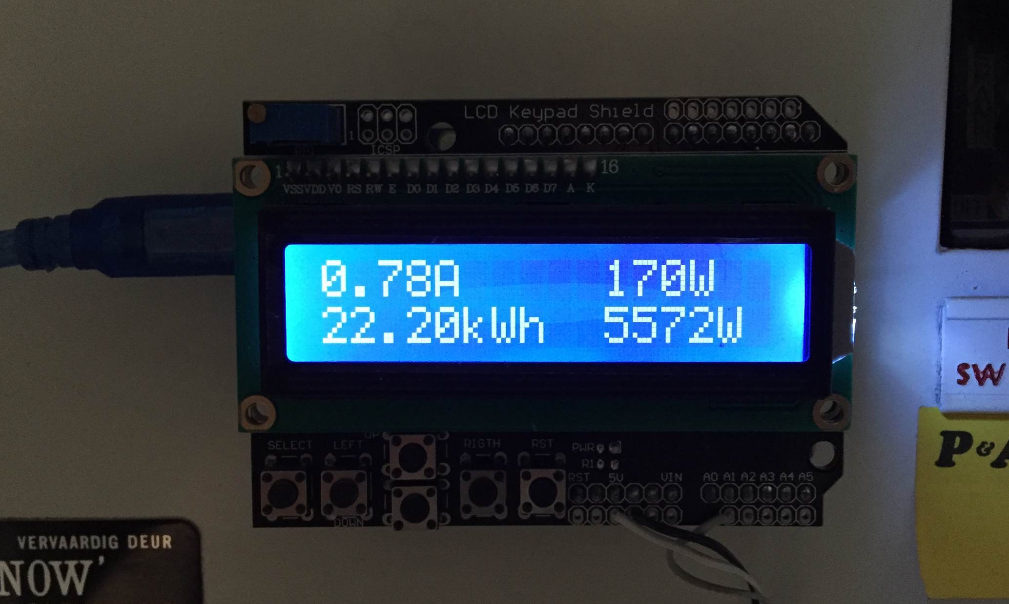
All the results can be visualized in the serial monitor or by using a LCD. I used a 16x2 character LCD to display all the results obtained in the previous steps.For schematics see the bread board circuit shown above. Connect LCD with ARDUINO as given bellow : LCD -> Arduino 1. VSS -> Arduino GND 2. VDD -> Arduino +5v 3. By using this Energy Meter, you can measure the power consumption of any home appliance. At the end of the project, I made a nice 3D-printed enclosure for this project. The goal of creating more awareness about energy consumption would be optimization and reduction in energy usage by the user. This would reduce their energy costs, as well as

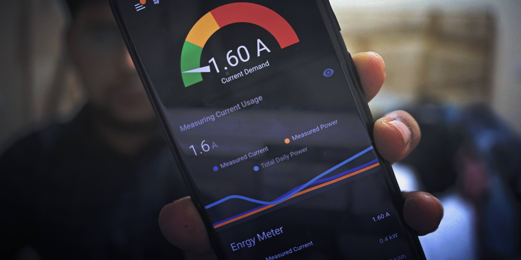
As energy prices rise and environmental concerns grow, understanding and managing home energy consumption has become more important than ever. Enter the Home Energy Monitoring System . With the help of an Arduino board, you can create a system to monitor energy usage, identify wastage, and save money—all while contributing to a greener planet. The INA219 is a DC current sensor that is commonly used in electronic projects to measure and monitor current flow. It is a high-precision sensor capable of measuring current up to 3.2A with a resolution of 0.1mA.. it operates using the principle of a shunt resistor, where a small shunt resistor is placed in series with the load, and the voltage across this resistor is measured to determine